The process vessels and drums
are cylindrical hollow vessels used in process plants as intermediate
containers. They are often used to provide surge volumes for liquid-vapour separations
on distillation columns or separating mixtures of immiscible liquids. Other uses are flash drums, condensate and other process liquid collectors and holding drums for additives
and chemicals.
The piping study
on drums shall consider the general requirements for drum plant
layout and provide information
required to locate nozzles, instruments, piping and controls for plat forming and operation / maintenance access.
In the first study of plot plan, platform
levels and details of vessel elevations are set from process requirements (net positive suction
head - NPSH, gravity feed,
barometric legs etc.) and from considerations of access for safe and convenient
operation and maintenance.
Methods of supporting vessels
and operating platforms are detailed. Access for lifting equipment or overhead hoists and trolley beams is arranged for removal of
motors, mixers and internal heat exchangers from
process vessels. A platform should always be
provided for the removal of such heavy items of equipment and for access to manholes, sight glass, light
glass etc.
In absense of any specific process requirement,
the drum should be located at a minimum height depending on the valves and fittings that are below the drum. Platforming should be kept to the minimum necessary to provide safe and suitable
access to manholes and operating valves.
A typical vertical drum and horizontal drum are
illustrated in sketches


Types Of Drum:
Drums are categorised as horizontal or vertical drums. Drums
internals are normally
demister pads, baffles,
vortex breakers and distribution piping.
Steam drums and deaerators
are usually proprietary items. Knock-out drums are used to separate condensate in the relieving discharges before going
to the flare stack. Headers to flare stacks from relief and blow
down valves and vents are run first to knockout
drum. It is recommended that the lines should run overhead
to the top of the drum and must slope at minimum
1:400 so that all condensate drain into
the drum.
The leg-supported drum is
illustrated in sketch

The saddle supported drum is
illustrated in sketch

The lug-supported drum is
illustrated in sketch

Leg-supported drums should not be used in reciprocating compressor circuits
Location Of Drums:
Drums are located within a
process unit either adjacent to related equipment (e.g. the reflux drum) or
as a stand alone unit (e.g. a condensate collection drum)
When operating within process sequence
of related items (e.g. pumps, condensers and towers) the drum should
be positioned to facilitate an orderly and economic piping
interconnection between itself and those items.
Within a conventional inline process unit, drums and their related
items are generally
located on either side of a
central piperack serviced by auxilliary roads for maintenance access.
In certain cases (e.g. flash
drums and deaerators), drums can be located above the piperack. In chemical plants, drums
are located at all levels
of enclosed or open structures.
Similar to towers, drum elevations are dictated by the NPSH
Drums for chemical collection systems are generally
located below ground level inside concrete pits.
To locate a drum,
the following information to be collected so that the level of drum can be finalised.
Drum dimensions
heads Support detail
NPSH requirements of pump Bottom
outlet size
Minimum clearances Location


Nozzle Location:
The following information is required to position the drum nozzles.
Process vessel Sketch
Instrument vessel sketch
Piping and Instrumentation diagrams Plant layout guidelines
Nozzle schedule or summary Insulation requirements
Unit Plot Plans
The preferred location for level instrument is
away from the turbulence at the liquid outlet
nozzle. Instrument nozzles shall be located in the quiet zone of the vessel ie. on the opposite
side of the weir
or baffle or near the vapour outlet.
Process nozzles should
be located at minimum from the tangent
line.
The relief valve should be
placed at a point on the top of the drum where the access platform can also provide
access to other valves connected
to the top of the drum.
The pressure connection
should be placed in the vapour space at the top of the drum, so that the face of the pressure gauge
is visible from the
ground or platform.
The temperature connection is usually close to the bottom
outlet, pointing towards
the access aisle or platform.
Manholes can be positioned at the top, at the side or at one end of the vessel.
Steam-out connections should be located
at the end opposite to the maintenance access with additional vent in the bottom section
of the drum as steam has a lower molecular weight.
The vent connection should
be located in the top section of the drum at the end opposite
the steam out connection.
The drain should
be located in the bottom section of the drum.
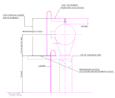
PLATFORM ARRANGEMENTS
A platform with good guard railings
is necessary for access if the manhole
is more than 3.5 m above grade.
Platforms on drums are
required for access to valves, instruments, blinds and maintenance accesses.
Platforming should be kept to the minimum necessary to provide safe and suitable
access to manholes and operating valves.


PIPING ARRANGEMENTS
Piping for process drums
should be arranged in conjunction with nozzle locations, platform arrangements
and the drums location to related equipment.
Piping should be positioned to facilitate the installation of supports with sufficient flexibility to absorb any excessive stresses
during operation.
Relief valves open to atmosphere on low elevated
horizontal or vertical
drums should be positioned to allow the discharge
piping to be routed to a convenient and safe location. Closed system relief valve should be located at a convenient platform adjacent to the drum above the relief valve header.
Normally, the liquid or vapour inlet is at the top and at one end of drum with liquid outlet on the bottom and vapour outlet at the top at opposite end.
Drain and vent lines may be located centrally
or at the ends if the drum is horizontal and if desired,
the drain valve may be placed at the low point of the outlet piping.
Horizontal drums should always have small slopes towards the drain points.
Level, pressure and temperature instruments are used to control the operation of the drum and should be in a position
for optimum operation and maintenance.
Level controllers, switches and gauges are
either located individually or grouped from a
common bridle or stand pipe. The
controller must be operable from grade or a platform, switches, gauges and pressure / temperature connections may be
operable from a ladder if no platform is available at the required elevation.
The fixed saddle shall be on the same side of the vessel as the pump suction nozzle.
In case of requirement
of an emergency isolation valves, these valves shall be located directly on the vessel nozzle.
The position of the support shall allow for the installation of the valve and
its actuator.
In order to gain access for maintenance and
operations purpose, level transmitter (LT) and
Level indicator (LT) nozzles shall be arranged
on either side of the access ladder
with their centres 400mm
from the ladder centerline.
All instruments shall be grouped on vessels and
drums such that the minimum number of ladders and platforms is required, without any
compromise on accessibility.


Nice post thanks for sharing..
ReplyDeletePipe Insulation Types
Cathodic Protection System
Pipe insulation types cathodic protection system
ReplyDeleteThank you for sharing this blog. If you’re looking for top Inline Drum Type Magnetic Separator Manufacturers in India,check out Magnatronix India. They offer high-quality solutions for various industrial needs.
ReplyDeleteThe points raised here are both practical and relevant, and buy fire protection equipment aligns well with the themes you’ve explored.
ReplyDelete
ReplyDeleteThe content is easy to understand and very helpful.
Wireless Temperature Transmitter Manufacturer