INTRODUCTION
Heat Exchangers are widely used equipments in the chemical, petrochemical and refinery type of plant. The control of heat within a plant
operation is done by direct heat application in
a furnace, or by heat exchange in a shell and tube exchanger / plate
heat exchanger. Types of heat exchanger may be Shell and Tube, Aircooled (Fin-Fan), Plate type or Coil type(spiral).
Various process duties of heat exchanger have an effect on the layout aspects viz.
a. Exchange of sensible heat between two process fluids.
b. Cooling with air or water.
c. Chilling with refrigerated liquid.
d. Heating with steam or hot water.
e. Condense by water or a cold process stream.
f. Vapourising by steam (e.g. column reboiler) or any
heat transfer liquid.
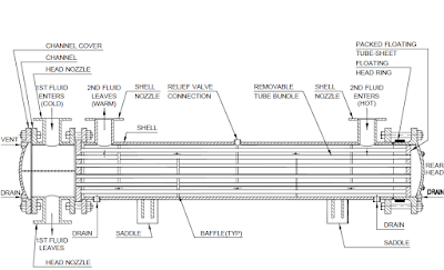
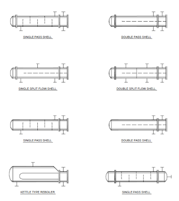
Fixed tube exchangers
are
used
when
the
temperature differences between shell side and tube side
fluid are small.
Floating head or U-type exchangers are used where there is a significant temperature
difference.
Kettle -type reboilers are used for evaporation
in case of
limiting
pressure drop, otherwise
vertical reboilers are used
for evaporation.
Plate heat exchangers
are generally
used in
low-pressure, low temperature
applications. The plate
exchanger occupies less space than shell and tube exchanger for
equivalent heat exchanger surface.
Aircoolers are
used for overhead
condensers of column
and consist of fin-tube bundles with a header
box to each end, having inlet on top of header-box
at one end and outlet on bottom
of header box at the other end.
For single pass arrangement of air-cooler
exchangers, inlet nozzles are mounted on the top of the header box
and the outlet nozzles are located at the opposite end and mounted on the bottom of the header box.For double pass arrangement, the
inlet and
outlet nozzles
are located
at the
same end.
LOCATION
Exchangers should be located
close to the
major equipment with which it is associated in PFD / P&ID. Reboilers are placed next to
their respective towers and condensers are placed over reflux drums. Exchangers between two distant pieces
of process equipment should be
placed at optimal points
in relationship to piperacks.
Most exchangers are to be located at grade
level with elevations to have a
clearance of 1m above Finished Ground Level (FGL). Elevated
exchangers may be necessary to fulfill the NPSH requirement of a downstream
centrifugal pump.
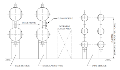
In case of large numbers
of heat exchangers,
they are grouped in one or more category
to save pipe work,
structural work, provision of lifting and maintenance facilities, platform requirement etc. Paired or
grouped exchnagers shall be
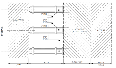
spaced to allow minimum 450mm preferrably 600mm between
the outside of adjacent channel or bonnet flanges to facilitate access to flange bolts during
maintenance. Adequate space shall be provided on
either side
of paired exchanger and
at both ends of grouped
exchanger for control and
operator access as illustrated.
Groups of exchangers should be generally
located by the alignment
of channel nozzles in a vertical plane so as to present
an aesthetic appearance.
The support saddle
with oblong holes for provision of thermal expansion are normally
located on the saddle farthest from the channel end but the final location depends on the plant layout and the stress analysis
of the connected piping.
Exchanger piping should be as direct and simple as possible
by considering alternatives such as arranging exchangers side by side / stacking them for reversing flows.
Exchangers are sometimes mounted on structures,
process columns and other equipment. Special arrangements for maintenance and tube cleaning should be provided in such cases.
ACCESS FOR OPERATION
& MAINTENANCE
Internals of heat exchanger require
periodic cleaning and repair. It is important that exchangers and the surrounding piping are arranged to facilitate
access to the internal parts.
Horizontal
clearance of at least 900mm should be left between exchangers flange to flange or exchanger flanges to piping. Where space is limited, clearance may be reduced between
alternate exchangers but in
no case clearance over insulation between
channel flanges shall be less
than 600mm.
The channel ends of exchangers
should face the local access road for tube bundle removal and the shell
cover should face the piperack. Pulled out bundles
should not extend over
main access road.
A typical
exchanger arrangement with clearance for
access, operation
and maintenance
is shown.
Access for tube bundle removal is usually 500mm more than the bundle length.
Mobile equipment should be used for handling
tube bundles and covers at grade level. Expensive
built-in facilities e.g. lifting
beams, monorails to be kept minimum.
The use of tube-bundle
extractor eliminates the need for permanent tube
bundle removal structures. These mechanisms
weigh around seven tons and are capable of pull
forces about 500,000lbs. The tube-bundle is held in position by crane and balanced
by the extractor's
leveling cradle and pulled out of its shell with pull rod attachments that use
hydraulic force.
For air-cooled exchangers, platform arrangements must suit maintenance
access requirements. Considerations
must be given to fin-tube bundle removal, tube rodding out at header
boxes, motor and fan access.
Provision
of easily removable spool pieces,
flanged elbows, break flanges or short pipe runs will be helpful for maintenance of exchangers.
Illustrations for exchanger location in unit
plot plan alongwith the provisions
of operating and maintenance
space, accessibility are shown.
STEPS TO DO HEAT EXCHANGER PIPING
Collect
the mech. spec. of the
heat exchanger.
Study the P&ID
around the heat exchanger and identify the relationship with the connected equipment
viz. column or reactor.
Note the special process
(functional) requirement along with the specific
arrangement details with respect to level or height difference from other related equipment like pumps.
Study the nozzle schedule, its position on the equipment and verify with P&ID.
Make a
sketch for the relative location and level. Find
out the tube cleaning space in
case shell &
tube Heat Exchanger as well as the maintenance space of tube bundle length.
Locate the control valve stations both for shell side and tube side fluids.
Decide the flanged joints location for replacement of Heat Exchanger / maintenance facility.
Check, in general, that
cooled streams flow downwards
and heated streams flow upwards.
This arrangement is mandatory when
there is a
change of phase, desirable when the streams are liquid but
not
important when the streams
are gas or vapour or
there is no super heating, super cooling.
Check, piping
should not foul with exchanger
removal either in the horizontal direction
for bundle-pulling
nor in the vertical for
whole exchanger removal.
Check, locally mounted PI, TI on equipment or process lines, sight glasses and level indicators are visible from access aisles and valves are accessible from the aisles.
Mark the
supports / support
arrangement on the piping study.
Ensure
accessibility /
operation
facility for all valves as
well as the clearance kept are not less than the
recommended minimum requirement
HEAT EXCHANGER PIPING
SHELL & TUB
After all the required
information has been collected for the
piping design of a heat exchanger, the first step is to outline clearance and working
space in front and around
both ends of the exchanger.
These working spaces should be kept clear of any
piping and accessories to facilitate channel, shell-cover and tube-bundle removal as well as maintenance
and
cleaning.
The free space at the side of horizontal shell can be used for placement of control stations.
The piping is elevated from
grade to have a clearance of 300mm above the grade level. The piping
connected to channel
head nozzles should be
furnished with
break flanges to
facilitate the
removal of
the channel head.
Steam lines connecting to
a header in the yard can be arranged on either
side of the exchanger centerline without increasing the pipe length.
Cooling-water lines, if under ground, should run
right under the lined-up channel nozzles
of all coolers.
Access to valve
hand wheels and instruments will influence the piping arrangement
around heat exchangers. Valve handwheels should be accessible
from grade and from a
convenient accessway. These accessways should be used for arranging manifolds, control valves and instruments.
PLATE & SPIRAL EXCHANGERS
Piping at spiral and plate exchangers
is also arranged
to allow opening
of covers and removal of plates.
Controls at the spiral exchanger are located
on the ends of the unit, clear of the cover plate swing area, piping attachment to cover plate nozzles of spiral exchanger will have break flanges.
Controls for plate exchanger
are located at the front and one side of the
exchanger. The piping is elevated to have clearance from grade as well as convenience for operation of valves.
AIR COOLERS
Piping
for air coolers are not routed
over tube banks or fans
and should be kept
clear of the designated space for motor maintenance.
Following Figure Show Location And Piping Arrangement.


No comments:
Post a Comment