Piping Engineering
Piping Engineering Articles Is Blog To Share Basic Piping Information And Piping Field Material.
Thursday, 4 August 2016
Monday, 1 August 2016
Piping Layout: PipeRack Piping Arrangement Drawing Part-1
The piperack general arrangement
is finalised during the development of overall plot plan. The exact width of
the piperack, numbers of levels and elevations, the access and maintenance
platforms are finalised during piperack piping study.
Normally, the piperack piping
study, with its structural and platform requirements is the first priority item
for detail engineering of a process unit. The piperack may be an integral part
of a process unit located in the middle of the unit or it may be an arterial part
connecting several services of other process unit.
The following data and drawings
are required to be studied before starting the detailed design of piperack
piping study:
Unit Plot Plan / Overall Plot
Plan, Piping and Instrumentation diagrams Plant layout specification, Client
specification, Material of construction, Fireproofing requirements
Wednesday, 27 July 2016
Piping Layout: TankFarm Piping And General Arrangement Drawing Part-2
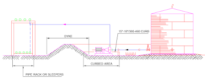
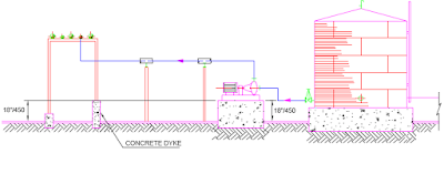
PUMP LOCATION IN TANKFARM
To determiine the optimum location of pumps, the potential hazards and
client preferrence shall be considered.
Fig. illustrates the location of pump within the dyke area with the
curb wall height of approx. 400-500mm.
This design protects the pump from minor spillage within the dyke and
enable the discharge piping to exit the dyke over the wall and there is no need
to have dyke penetration seals.
The piping outside the dyke may run on a piperack or sleepers.The pumps
located outside the dyke area are illustrated in Fig.
Tank outlet piping can either penetrate the dyke or pass over the dyke in
case the minimum liquid level in the tank do cause cavitation in the pump.
Tuesday, 26 July 2016
Piping Layout: TankFarm Piping And General Arrangement Drawing Part-1
The study of the tankfarm consisting of a group of tanks shall be carried
out keeping the following basic points in consideration.
1. Grouping of tanks,
2. Specification of the content.
3. Capacity of tanks
4. Nature of hazard - fire
- toxic
- explosive
- corrosive
- bulk handling loading
5. unloading
6. Statutory distance
7. Requirement of Dykewall or curbing
8. Dykewall height or curb height calculation
9. Location of Pumps - inside dyke area
- outside dyke area
10. Approach to tank nozzles with valve
11. Approach to tank roof
12. Drainage of dyke area - Sump and pump
13. Road around tankfarm
14. Fire hydrant / monitor requirement
15. Underground system connected to specific system of treatment / disposal
Thursday, 21 April 2016
Lesson 2 : Basic Of Pipe Stress Analysis Using Caesar II (Model Input Practise)
If you have any doubt than comment...
Tuesday, 8 March 2016
Lesson 1 : Basic Of Pipe Stress Analysis Using Caesar II
From this tutorial you can learn basic concept of caesar 2 software, how to start new file and to create custom unit file for different project.
This tutorial also prove basic theory of strength of material.(F=K*X)
Example show cantilever beam of 10m and having 2mm deflection at one end, other end is fix called as anchor in caesar.
Step1: Create new unit file for this tutorial as shown in video.
Step2: Make 10000mm long pipe in -x direction select a106 grb as a pipe material.
Step3: Select Node number 10 as anchor point and give -2mm displacement in y direction to node number 20.
Step4: Now check for error than run analysis, caesar will show you default load case sus, ope and expansion.
Step5: You can create new load case for only displacement as we required force due to deflection.
Step6: Now see the displacement and force report.
Conclusion: To make 2mm deflection how much force required, that we can see from analysis. and you can also make manual calculation for that to compare using following formula.
F=Kx
where K= 3EI/L^3 N/mm
x= 2mm
If you have any doubt than comment...
Thursday, 7 January 2016
Subscribe to:
Comments (Atom)


